Test Geometry
Test Geometry creates sample bodies and paths for calibration prints. The shape is chosen from the dropdown on the component. Using the same shape for every run of a test series makes the measurements comparable.
Three families:
- Free shapes - cylinder, vase, twisted vase, frustum, wall and box, sized from the component’s own inputs.
- Standard specimens - flexural and compressive test bodies at the nominal dimensions of DIN EN and ASTM standards, so a printed batch can be tested against a published method instead of an ad-hoc block.
- Extrusion test path - a zig-zag line for flow and cornering checks.
Panel: 6 Calibrate. Nickname: TestGeo. Compute button: no (runs on every change).
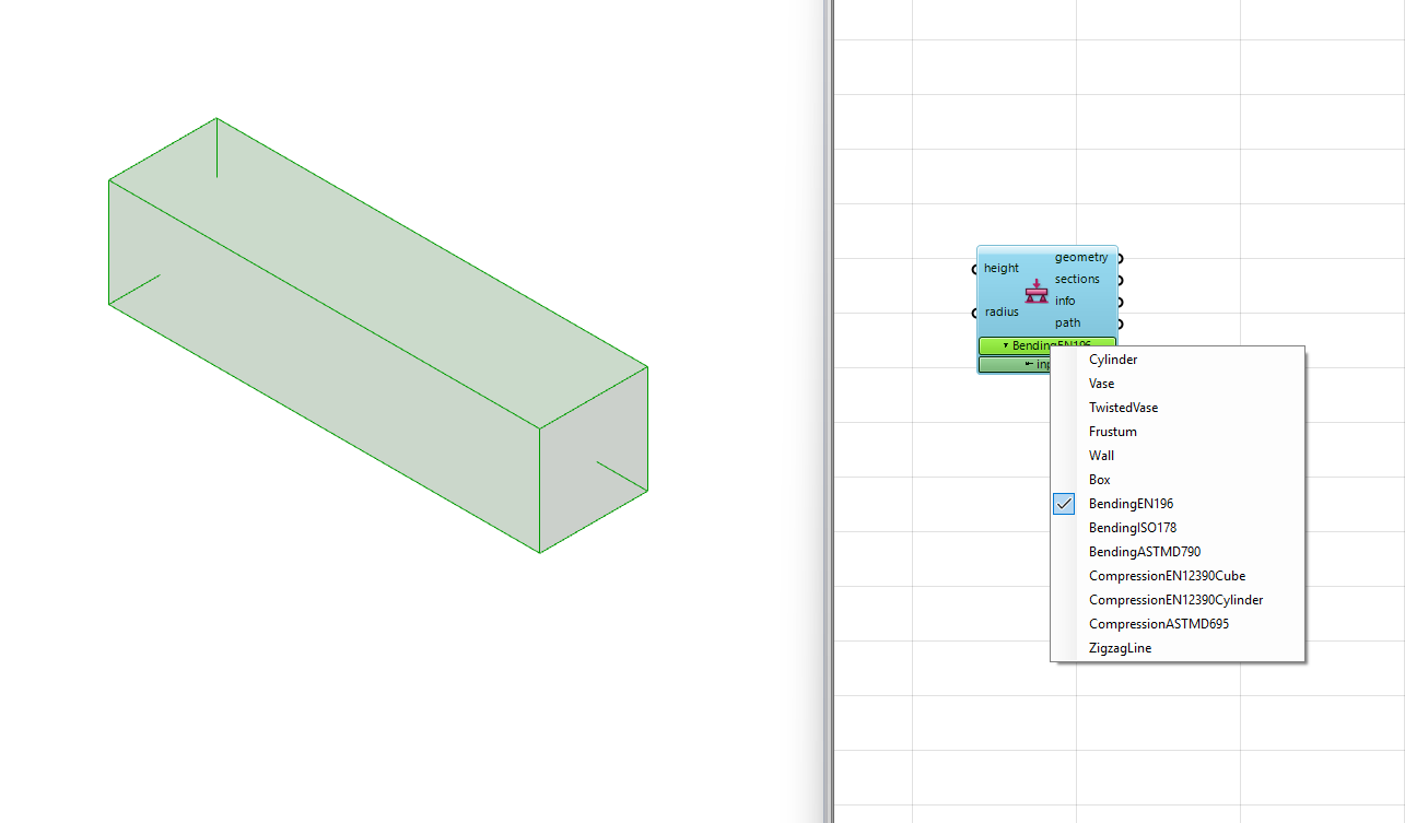
Inputs
| Name | Type | Default | Description |
|---|---|---|---|
height |
Number | 100 | Overall sample height in mm |
radius |
Number | 40 | Base radius, mm, for cylinder, vase and frustum |
Optional group: Base-plane input
Right-click the component to switch this group on. The inputs appear only while the group is enabled.
| Name | Type | Description |
|---|---|---|
plane |
Plane | Base plane (default World XY) |
Optional group: Profile detail inputs (waves, twist, sides, frustum ratio)
Right-click the component to switch this group on. The inputs appear only while the group is enabled.
| Name | Type | Default | Description |
|---|---|---|---|
waveAmp |
Number | 0.15 | Vase: radial wave amplitude as fraction of radius (0 = straight) |
waveCount |
Number | 3 | Vase: number of radial waves over the height |
twistDeg |
Number | 90 | Twisted vase: total twist over the height, deg |
sides |
Integer | 0 | Vase or frustum section sides (0 to 2 = circle, 3 or more = polygon, twisted vase defaults to 6) |
topRatio |
Number | 0.6 | Frustum: top radius divided by base radius |
Optional group: Wall / box dimension inputs
Right-click the component to switch this group on. The inputs appear only while the group is enabled.
| Name | Type | Default | Description |
|---|---|---|---|
length |
Number | 150 | Wall length or square box side length in mm |
width |
Number | 8 | Wall thickness in mm (the box uses length for both sides) |
Optional group: Standard specimen scale (DIN EN / ASTM shapes)
Right-click the component to switch this group on. The inputs appear only while the group is enabled.
| Name | Type | Default | Description |
|---|---|---|---|
specimenScale |
Number | 1 | Uniform multiplier for standard specimen dimensions (1 = nominal size) |
Optional group: Extrusion test path inputs (zig-zag line)
Right-click the component to switch this group on. The inputs appear only while the group is enabled.
| Name | Type | Default | Description |
|---|---|---|---|
zzLength |
Number | 150 | Zigzag: length of one straight pass, mm |
zzPitch |
Number | 10 | Zigzag: distance between passes, mm. Set it to the layer spacing you are testing |
zzPasses |
Integer | 8 | Number of straight zigzag passes, at least 2 |
zzLayers |
Integer | 1 | Number of stacked zigzag layers, at least 1 |
zzLayerHeight |
Number | 3 | Vertical spacing between zigzag layers in mm, used when zzLayers exceeds 1 |
zzArcTurns |
Boolean | true | Use semicircular zigzag turns when true, or sharp reversals when false |
Outputs
| Name | Type | Description |
|---|---|---|
geometry |
Brep | Test geometry as a Brep. Wire into the slicer |
sections |
Curve (list) | Cross section curves used for the loft. Empty for box and wall |
info |
Text | Shape summary |
path |
Curve (list) | Zigzag toolpath in Rhino document units for G-code Generator (empty for solid shapes) |
Standard specimens
| Shape | Standard | Nominal size (mm) | Test |
|---|---|---|---|
BendingEN196 |
DIN EN 196-1 | 160 × 40 × 40, span 100 | three-point bending of cement mortar; the broken halves are then crushed between 40 × 40 mm platens |
BendingISO178 |
DIN EN ISO 178 | 80 × 10 × 4, span 64 | three-point bending of plastics, 16:1 span-to-depth |
BendingASTMD790 |
ASTM D790 | 127 × 12.7 × 3.2, span 51.2 | three-point bending of plastics, 16:1 span-to-depth |
CompressionEN12390Cube |
DIN EN 12390-1/-3 | 150 cube | compressive strength of hardened concrete |
CompressionEN12390Cylinder |
DIN EN 12390-1/-3 | Ø150 × 300 | compressive strength of hardened concrete |
CompressionASTMD695 |
ASTM D695 | 12.7 × 12.7 × 25.4 | compression of rigid plastics, loaded along the long axis |
The shapes and tolerances of the concrete specimens are specified in EN 12390-1; EN 12390-3 is the compression test method. Both parts are named because you need the first to cast the body and the second to test it.
For a cement-based print, EN 196-1 is the closest fit: it is the reference method for cementitious binders, and the same prism gives you both the flexural and (from its halves) the compressive strength.
What the component does not claim
These are nominal geometries only. Nothing here asserts that a printed body is a valid specimen under the standard. Layer orientation, surface finish, curing and the anisotropy of an extruded part all sit outside the geometry, and every one of these standards was written for cast or moulded material. Use them to make a test series internally comparable and to talk to a testing lab in its own dimensions - not to claim conformity.
specimenScale exists because the plastics bars are unprintable at nominal
size: an ISO 178 bar is 4 mm thick and an ASTM D790 bar 3.2 mm, both thinner
than a single LDM layer. The component says so with a remark, and says again
that a scaled body is no longer at the standard’s dimensions, so its results
are comparable within your own series but not to the standard.
The zig-zag extrusion test
A boustrophedon line: straight passes joined alternately at each end,
optionally stacked. It is a toolpath, not a solid, so geometry is
empty on purpose and the line comes out of path. Wire that straight into
G-code Generator; sending it through the slicer would try to
section a curve.
The reversals are the point of the test. A straight line only shows
steady-state flow; the turns show whether the layer tears on the inside of
the corner and over-deposits on the outside. Rounded turns (zzArcTurns,
a half circle of radius zzPitch/2) keep the tangent continuous and are
the gentler case; sharp turns are the harsher one. Set zzPitch to the
layer spacing you actually intend to print at, and the gaps or overlaps
between passes tell you whether the flow matches the spacing.
Stacked layers alternate their start side, so a stack does not put its seam at the same end on every layer.
Back to Components.